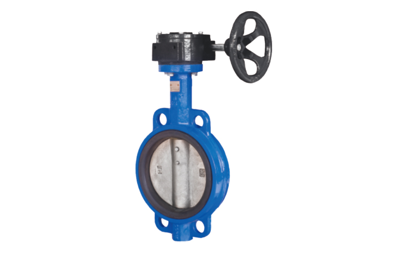
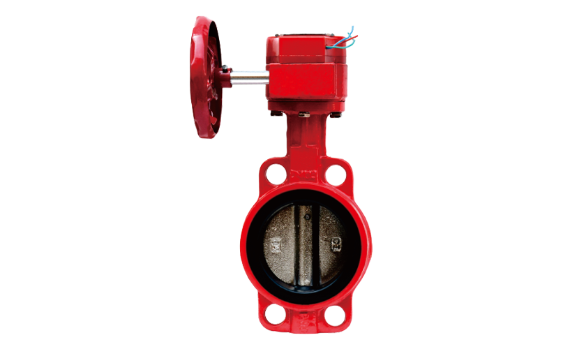
The fire clamp signal butterfly valve is a key valve used in the fire protection system for real-time monitoring and rapid control of water flow. Its core features include:
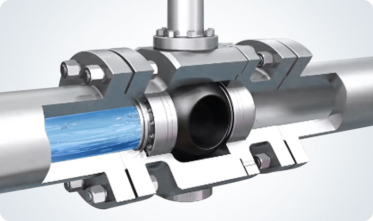
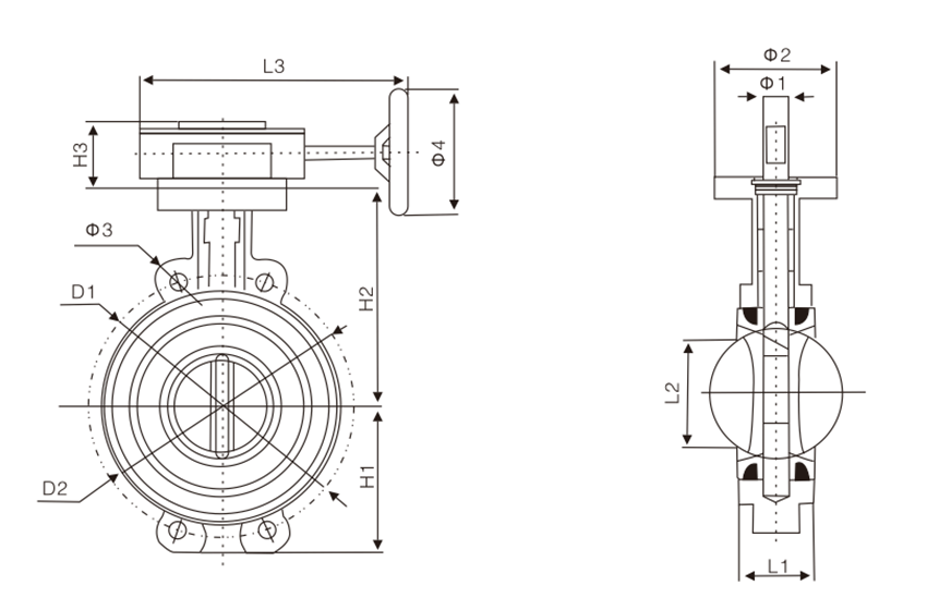
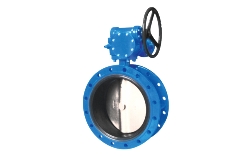
Structure and Installation: Adopting a mid line clamp design, the valve body has no flange, and is fixed to the pipeline flange through bolt through lugs. The installation is compact and suitable for narrow spaces;
Functional features:
Built in micro switches or sensors provide real-time feedback on valve opening and closing status to the fire control system, ensuring automatic alarm for abnormal conditions;
Bidirectional sealing structure (such as rubber+metal composite seal), pressure resistance range PN10-PN16, suitable for low to medium pressure requirements of fire water systems;
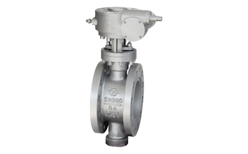
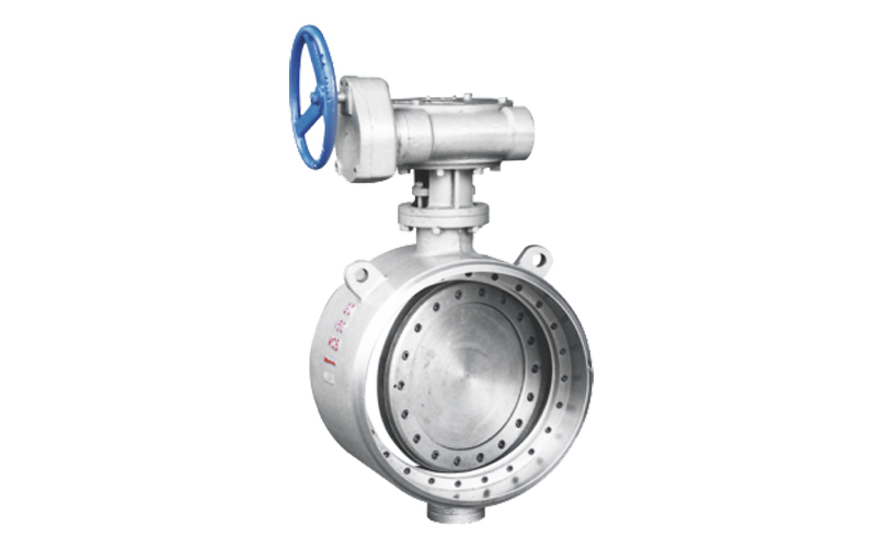
Operation and compatibility: Supports manual+electric/pneumatic dual drive mode, 90 ° quick opening and closing (≤ 10 seconds), and can be manually operated for emergency in case of power failure;
Materials and reliability: The valve body and seals are made of corrosion-resistant materials such as stainless steel and fluororubber to reduce the risk of leakage and extend their service life;
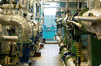
Application scenario: Dedicated to key nodes that require real-time monitoring and rapid response, such as automatic sprinkler systems, fire hydrant pipelines, and fire pump inlets and outlets.
This valve is linked to the fire alarm host through a signal output interface (dry contact or 4-20mA), and complies with fire certification standards such as UL/FM/CCFF.


Part Name | valve body | Valve shaft | butterfly valve disc | valve seat | Valve seat backrest | bushing | sealing ring | round washer | open loop | retaining ring |
material | Ductile iron, cast steel | 410/316 | ductile iron | EPDM, | phenolic | Bronze, polytetrafluoroethylene | NBR. | 16/Brass | 16/Brass | spring steel |

Nominal diameter DN (mm) | H1 | H2 | H3 | D1 | D2 | L1 | L2 | L3 | Φ1 | Φ2 | Φ3 | Φ4 |
50 | 70 | 130 | 68 | 120 | 95 | 43 | 32 | 245 | 12.6 | 70 | 23 | 152 |
65 | 76 | 143 | 68 | 136 | 109 | 46 | 47 | 245 | 12.6 | 70 | 26-3 | 152 |
80 | 86 | 155 | 68 | 160 | 124 | 46 | 65 | 245 | 12.6 | 70 | 18 | 152 |
100 | 104 | 170 | 68 | 182 | 153 | 52 | 91 | 245 | 15.8 | 90 | 24-5 | 152 |
125 | 118 | 190 | 68 | 215 | 179 | 56 | 112 | 245 | 19 | 90 | 23 | 152 |
150 | 132 | 210 | 68 | 238 | 206 | 56 | 146 | 245 | 19 | 90 | 25 | 152 |
200 | 167 | 243 | 85 | 295 | 264 | 60 | 194 | 400 | 22.1 | 115 | 25 | 300 |
250 | 198 | 282 | 85 | 357 | 316 | 68 | 242 | 400 | 28.5 | 115 | 29 | 300 |
300 | 239 | 310 | 52 | 407 | 373 | 68 | 292 | 400 | 31.7 | 140 | 29 | 305 |
350 | 267 | 368 | 82 | 467 | 436 | 78 | 325 | 400 | 31.7 | 140 | 30 | 305 |
400 | 309 | 400 | 212 | 515 | 488 | 102 | 380 | 431 | 33.15 | 197 | 26-30 | 290 |
Note: Flange drilling shall comply with GB/T17241.6-1998 standard. PN2.0 specifications and sizes are not listed. If there are special specification requirements, please contact the sales department.
Oil and gas transportation involves multiple modes such as pipelines and ships, and is the core link of the energy supply chain.

The control of chemical raw materials covers the entire process of mining, storage, and production, ensuring safety and process stability.

High temperature steam pipelines are the core of energy transmission in power systems, supporting the efficient operation of thermal and nuclear power plants.

Valves control fluids in multiple industries such as new energy and electronics, ensuring safe and efficient production.


