

Valve CAD drawings are an essential component in the design and manufacturing process of valves. These detailed technical documents provide crucial information about the dimensions, materials, and specifications of valves, ensuring that they are manufactured and installed correctly. In this comprehensive guide, we will delve into the world of Valve CAD drawings, exploring their importance, components, and how they are used in the industry.
**Introduction**
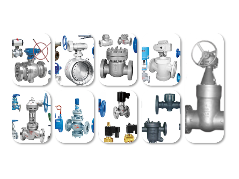
Valves are vital components in various industries, including oil and gas, water treatment, and chemical processing. They are used to control the flow of fluids, gases, and steam. The design and manufacturing of valves require precise engineering and attention to detail. This is where Valve CAD drawings come into play. These drawings serve as a blueprint for the production of valves, ensuring that they meet the required specifications and perform their intended function.
**The Importance of Valve CAD Drawings**
Valve CAD drawings are crucial for several reasons:
1. **Design Accuracy**: CAD drawings provide engineers with a detailed representation of the valve, allowing them to ensure that the design meets the required specifications and performance criteria. 2. **Manufacturing Process**: CAD drawings serve as a guide for manufacturers, ensuring that the valve is produced with the correct dimensions and materials. 3. **Quality Control**: CAD drawings enable quality control personnel to inspect the valve during the manufacturing process, ensuring that it meets the required standards. 4. **Installation and Maintenance**: CAD drawings provide valuable information for installers and maintenance personnel, ensuring that the valve is installed and maintained correctly.
**Components of Valve CAD Drawings**
Valve CAD drawings typically consist of the following components:
1. **General Information**: This section includes the valve type, size, and material specifications. 2. **Dimensions**: Detailed dimensions of the valve, including the body, bonnet, and other components. 3. **Materials**: Information about the materials used in the valve, such as the type of steel, alloy, or plastic. 4. **Connection Details**: Information about the type of connection used, such as flanged,焊接, or threaded. 5. **Pressure and Temperature Ratings**: The maximum pressure and temperature that the valve can handle. 6. **Valve Trim**: Information about the internal components of the valve, such as the seat, disc, and stem. 7. **Special Features**: Any unique features or design considerations that may affect the valve's performance.
**How Valve CAD Drawings are Used in the Industry**
Valve CAD drawings are used in various stages of the valve manufacturing and installation process:
1. **Design Phase**: Engineers use CAD drawings to design the valve, ensuring that it meets the required specifications and performance criteria. 2. **Manufacturing Phase**: Manufacturers use CAD drawings to produce the valve, ensuring that it is manufactured with the correct dimensions and materials. 3. **Quality Control**: Quality control personnel use CAD drawings to inspect the valve during the manufacturing process, ensuring that it meets the required standards. 4. **Installation Phase**: Installers use CAD drawings to install the valve correctly, ensuring that it operates as intended. 5. **Maintenance Phase**: Maintenance personnel use CAD drawings to maintain the valve, ensuring that it continues to perform its intended function.
**Conclusion**
Valve CAD drawings are an essential tool in the design, manufacturing, and installation of valves. These detailed technical documents provide crucial information about the dimensions, materials, and specifications of valves, ensuring that they are manufactured and installed correctly. By understanding the importance and components of Valve CAD drawings, engineers, manufacturers, and maintenance personnel can work together to ensure the successful implementation of valves in various industries.


 Chat Oline